How Does a Hydraulic Hammer Work
When you need to break up stubborn concrete or pavement, a hydraulic hammer is a perfect tool for the job. This handy piece of equipment utilizes fluid pressure to create powerful repeated blows, allowing it to demolish even the most solid surfaces quickly. But how does a hydraulic hammer work, and what makes it so better than other demolition tools? Keep reading to find out!
If you’ve ever seen a hydraulic hammer in action, then you know just how powerful and impressive they are. But have you ever stopped to ask yourself how it works? In this blog post, we’re going to take a closer look at the inner workings of a hydraulic hammer and explain how it can achieve such remarkable results. Stay tuned!

What Is a Hydraulic Hammer?
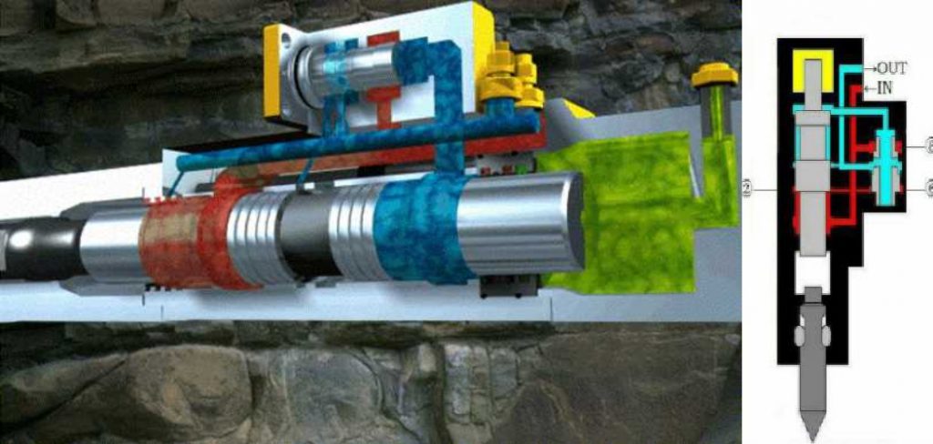
A hydraulic hammer is a construction equipment that uses liquid under pressure to produce high-impact blows. Hydraulic hammers come in many varieties, from small handheld models to large axle-breaking machines.
In all cases, though, the high-pressure liquid drives air out of a chamber and compresses the air in front of a piston. When the pressure on the piston is released, it shoots forward and delivers a powerful blow. Hydraulic hammers can drill holes in concrete, pulverize rock or asphalt, break up old concrete to make new construction, and demolish objects such as cars and trucks.
How Does a Hydraulic Hammer Work?
A piston creates the impact of a hydraulic hammer. This is a long metal cylinder with one sealed end and the other open. The outer side of the piston has several rings attached to it, five or six in most cases. These are evenly spaced across the circumference of the piston. They fit into grooves that have been cut into the pressure chamber.
These grooves are cut at a steep angle. When the piston is inside the pressure chamber, these grooves face up toward the chamber ceiling. When hydraulic fluid is forced into the pressurized chamber, it flows past the piston rings and enters tiny holes in them. This makes them expand outward against their grooves, pressing tightly against the walls of the chamber and making it impossible for them to move.
At the same time, increased pressure on one side of the piston causes a build-up of force between it and whatever is holding it in place. In most cases, another metal cylinder acts as a counterweight to keep the action even. Depending on how the machine is designed, this counterweight may swing in the opposite direction of the piston when it hits its release point, or it may stay stationary.
Hydraulic Breaker Hammer Working Principle: 6 Facts to Know
1. Sledgehammer: A sledgehammer is a large tool designed to break up rock or other materials.
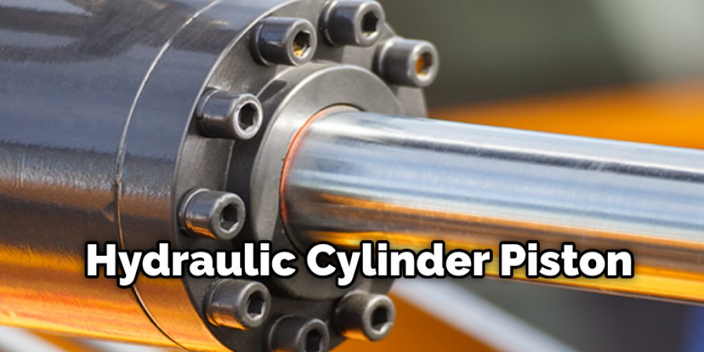
2. Hydraulic Cylinder: A hydraulic cylinder consists of two major parts, the upper part being the piston rod and the lower being the cylinder barrel. The dual-walled construction allows for use as a hydraulic fluid reservoir while providing structural support where needed.
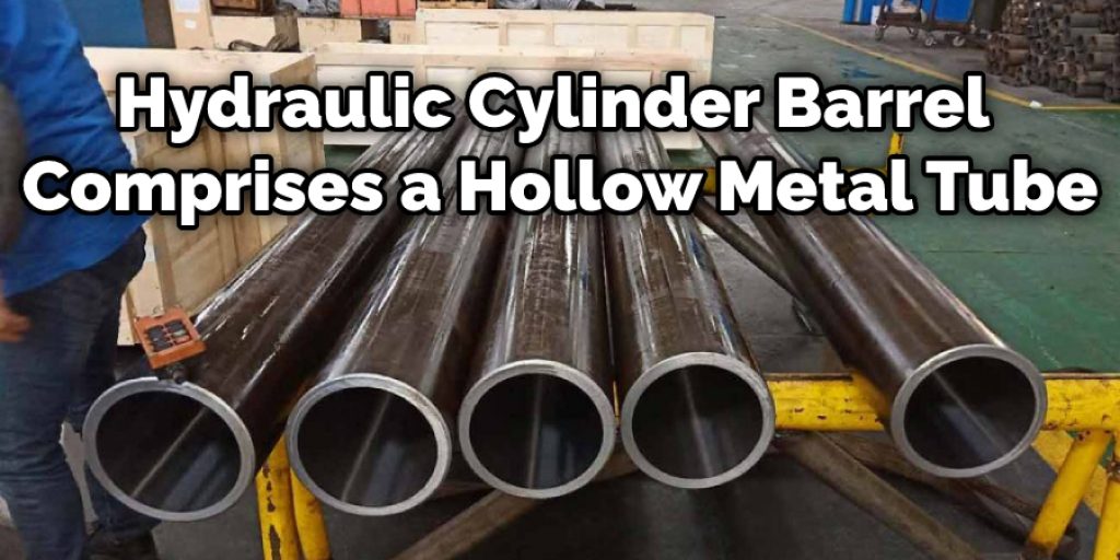
3. Hydraulic Cylinder Barrel: Generally, the cylinder barrel comprises a hollow metal tube equal in length to its piston travel distance. The inner side of the cylinder barrel would be slightly larger than the outer circumference of the upper section of the piston rod. The gap between these two components forms an area suitable for holding hydraulic fluid.

4. Hydraulic Fluid: A hydraulic fluid is a liquid whose pressure is controlled by the height of its container, the device it powers, or other factors that vary its volume in some way. The ability to vary its volume gives the hydraulic fluid additional versatility over other liquids.
5. Blowout Energy: Blowout energy is the kinetic energy of a moving body at the moment just before it starts to move. At that point, its potential energy has already been converted into two other forms: rotational or linear kinetic energy.
6. Impact Frequency: Impact frequency is the amount of time that elapses between successive impacts. It is different from striking frequency, the number of strikes per unit time (usually one strike per second).
Hydraulic Breaker Structure
1. Back Head (Nitrogen Chamber):
It is a steel structure with the opening and closing of the valves on top. Nitrogen gas is pumped into this chamber, forcing the pistons to move back & forth.
2. Pilot Rod:
A long slender metal tube leads from the hydraulic pump to one end of each piston to transfer fluid pressure force to the piston.
3. Cylinders (Pistons):
It is a long slender metal tube with two sealed ends since it is completely hollow. These cylinders are attached to the back head mentioned above through their respective hinge pins that allow them to move freely in a backward & forward motion but limit them from moving sideways. In addition, each tube has a piston inside, which is attached to the top and bottom ends of the tube, therefore making it so that fluid pressure forces and moves only the piston back and forth.

4. Cylinder Assembly:
The piston is attached to the bottom end of the cylinder and has a floating ring that fits into a groove on each side. It also contains a lower gasket between it and the hydraulic chamber, making a tight seal. The top end of this assembly includes an upper gasket followed by a mounted hard metal conical seat.
5. Front Head:
The front head is a steel structure that includes the moving jaws used to grip the object being smashed. It also includes two hinge pins that hold everything in place and pushrods that have their own o-rings that create tight seals between them and where they meet with the back & front heads.
How to Select Hydraulic Breaker for Excavator?
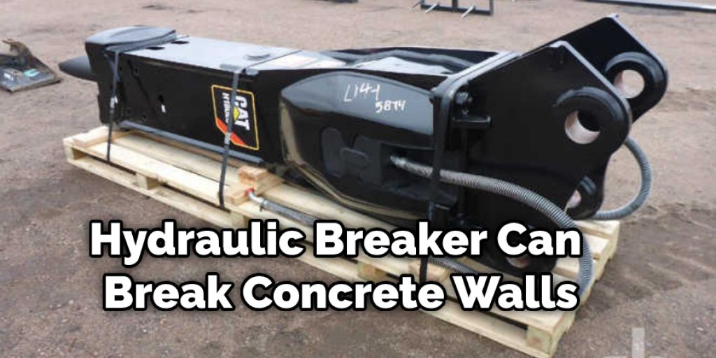
The hydraulic excavator breaker is the most powerful tool in an excavator’s bucket. This tool can break heavily reinforced concrete walls, demolish buildings, or even break up boulders to make rocks for roads. Therefore, selecting the right hydraulic breaker is essential when purchasing one. A top number of brands sell various models of hydraulic excavator breakers.
The model number of the breaker you select needs to fit the host machine so that it is not too heavy for your excavator but can still deliver sufficient power to get the job done. The two most important factors in selecting an appropriate hydraulic excavator breaker for your machine are weight and size. Hydraulic excavator breakers are available in various sizes, beginning at about 200 pounds and increasing to over 2,000 pounds. First, you must find one that is appropriate for your excavator.

Conclusion
A hydraulic hammer, also known as a pile driver or pneumatic hammer, is used to drive piles into the ground. The hydraulic hammer uses a piston to create pressure in a cylinder, releasing and driving the pile downwards. The force of the impact can be regulated by adjusting the amount of air entering the chamber.
Hydraulic hammers are often used in construction projects where large piles need to be driven deep into the ground quickly and efficiently. We hope this blog post has helped answer how does a hydraulic hammer works. If you have anything in mind or want to know more, then feel free to comment below!


